DBC signal byte order: Intel vs Motorola, start bit and scaling
How an SG_ line maps bits of a CAN payload into a physical engineering value.
Updated 2026-11-05
DBC is a plain-text database format introduced by Vector for describing CAN networks. It does not carry the frames themselves; it describes how to interpret them. A message is declared with BO_ followed by the identifier, a name, the DLC and the transmitting node. Signals hang off that message with SG_ lines, while CM_ adds comments, BA_ attaches attributes such as cycle time or a GenMsgCycleTime value, VAL_ defines value tables for enumerations, and BO_TX_BU_ lists additional transmitters. Files in the wild are frequently encoded in Windows-1252 or GBK, so a parser that assumes UTF-8 will quietly corrupt signal names and comments; a tolerant decoder is part of reading DBC reliably.
One SG_ line carries almost everything needed to extract a value: the signal name, a start bit, a bit length, a byte-order marker, a signedness marker, factor and offset, minimum and maximum, a unit and a list of receiving nodes. The marker is either @1 for Intel (little-endian) or @0 for Motorola (big-endian). A trailing minus sign means the raw integer is signed and must be sign-extended before scaling. The parentheses hold factor and offset, and the square brackets hold the display range. Everything after that is metadata: it helps a human read the value but does not change the bits on the wire.
Anatomy of an SG_ line
BO_ 256 EngineData: 8 ECU
 SG_ EngSpeed : 3|16@1+ (0.25,0) [0|16383] "rpm" Dashboard
Read the example as: signal EngSpeed starts at bit 3, is 16 bits long, uses Intel byte order, is unsigned, and converts to rpm with a factor of 0.25 and no offset. The physical value is always raw × factor + offset, applied after the raw integer has been extracted and sign-extended if needed. Because the start bit refers to a position inside the payload, its meaning depends on the byte order: with @1 the signal continues from the least significant bit of byte 0 upward across byte boundaries, while with @0 it begins at the most significant bit of the start position and walks downward into the next byte. Swapping the marker therefore produces a completely different number, not merely a byte swap.
Why the byte order changes everything
Compare how the same 16-bit signal occupies bits in Intel and Motorola layouts
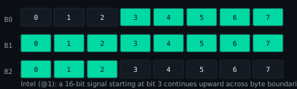
Consider a 16-bit signal starting at bit 3. In Intel layout the first five bits live in the upper half of byte 0, the next eight fill byte 1, and the last three sit in the low half of byte 2. In Motorola layout the signal consumes byte 0 bits 3 down to 0, then jumps to byte 1 bit 7 and continues downward through bit 0, then takes byte 2 bits 7 down to 4. Both descriptions produce 16 bits, but they address different physical cells. This is the single most common source of wrong values when a database is translated by hand, and it is why a viewer should show the extracted raw value alongside the scaled physical value so that a mistake is visible immediately.
Common keywords in a DBC file
- BO_ — message (identifier, name, DLC, transmitter)
- SG_ — signal (start bit, length, byte order, signedness, scaling, unit)
- CM_ — comment attached to a message, signal or node
- BA_ / BA_DEF_ — attribute values and their definitions
- VAL_ — symbolic value table, e.g. 0 Off, 1 On
- BO_TX_BU_ — additional transmitting nodes for a message
Real databases are messy: duplicate identifiers, missing BA_DEF_ definitions, non-ASCII comments, signals whose declared length exceeds the DLC, and lines split across encodings. A useful viewer reports these as diagnostics instead of refusing to open the whole file, because the engineer usually needs the 95 percent that is valid to keep working. Exporting the parsed result to CSV or XLSX then gives one row per signal with message id, name, start bit, length, byte order, factor, offset, unit, comment and value table — a reviewable artefact that can be diffed against the next revision of the database.
Try it in the viewer
Open a sample file or drop your own DBC/A2L file. Parsing happens entirely in this browser; nothing is uploaded.
Open the viewerFrequently asked questions
What do @1 and @0 mean in an SG_ line?
@1 is Intel (little-endian), @0 is Motorola (big-endian). They differ in how bits continue across byte boundaries.
Where do factor and offset apply?
After extracting the raw integer: physical = raw × factor + offset. Unit, minimum and maximum are metadata for display.
Related guides
Which topic should come next? Send a short email — no forms, no tracking.